Lesson 4: Designing a Home Page
Upon completion of this unit, you should be able to:
- Understand the basics of site architecture and document sizing.
- Use a background (comp) image as a guide.
- Create and use graphic and movie clip symbols.
- Create and use layers and guides.
- Import and place JPEG files.
- Create a template movie clip.
The Gallery San Luis Home Page Requirements
Gallery San Luis is so happy with the logo you created that they would like you to design a Web site for them, all in Macromedia Flash. They would like the site to contain the following:
- A Home page that is both appealing and speaks photography.
- A Featured Artist page with a slide show of photographs and featured photographer information (and perhaps video interviews with the featured artists).
- An Events page for requesting tickets to gallery events.
- An animated Map page to indicate where the gallery is located.
- Sound incorporated on buttons.
- Slick transitions between pages.
- An overall photography metaphor for the site.
 Site Architecture Site Architecture
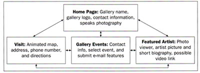
As with any Web design lesson, so many site needs can seem overwhelming, so you must start with the most basic elements of the design. The site architecture diagram shown in Figure 4-1 gives a basic idea of what the Web site will include (arrows indicate links).
FIGURE 4-1a:
Gallery San Luis site architecture diagram
Sizing a Home Page
One of the major considerations for the design is size. The Gallery has indicated that they wish to target computers running Microsoft Internet Explorer set to at least an 800 x 600 display resolution. When designing for such resolutions, you must leave extra space for the browser's toolbar and title bar to display. For Internet Explorer windows, you have the actual display regions listed in Table 4-1b.
TABLE 4-1b:
Internet Explorer display regions
Screen Resolution |
Actual Display Area |
640 x 480 |
620 x 318 |
800 x 600 |
780 x 438 |
1024 x 768 |
1004 x 606 |
1280 x 1024 |
1260 x 862 |
When it's time to publish the movie for the final site, we will discuss these size issues further (see Lesson 13, Publishing a Macromedia Flash Movie).
-
STEP-BY-STEP 4.1 Setting Up a New Workspace
- Launch Flash and create a new Flash Document
- Save the document as home followed by your initials in the Flash 2004 Document format. Make sure you save the movie in your build_GallerySanLuis folder.
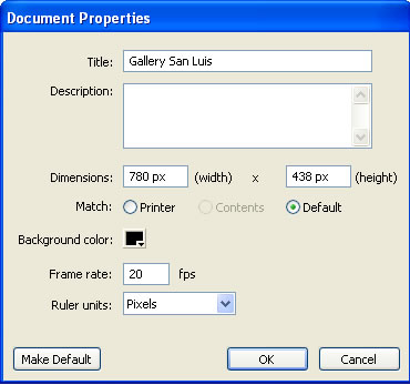
- Click the Modify menu, and then click Document. The Document Properties window opens, where you can set the size, speed, frame rate, and background color of your document.
- As shown in Figure 4-1c, title your document Gallery San Luis,change the dimensions of the document to 780 x 438 pixels (the document is now set for the Internet Explorer browser in 800 x 600 pixels); change the background color to black (#000000); change the frame rate to 20; and then click OK.
FIGURE 42
Document Properties window configured for 800 x 600 display
- Save your changes and remain in this screen for the next Step-by-Step.
Drawing in Flash
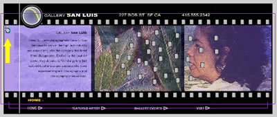
While focusing on construction of the home page, your guiding principles are the needs of the client. "A page that speaks photography" implies that the first page will have photographs and maybe even look like some sort of photographic device. You also know that you must include some basic functional and content components: the name of the gallery, a logo, contact information, and links to the other pages in the site. The first step in design is to draw on paper a rough design of what the site would look like.
You can use an image-processing program such as Macromedia Fireworks to construct a mock or rough design of the site like the one shown in Figure 4-3.
FIGURE 4-3a:
Mock image of the site
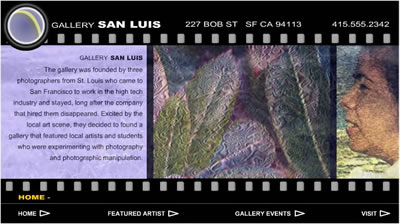
Like a professional designer, you will use this image as a guide when you build the site in Flash. Many designers put such an image in the background while
building in Flash and then delete the image later. Before drawing, you need to configure the workspace for the size and type of media you are building.
From the design sketch, you have the dimensions for the home page. Sizing a document is the first step in creating a Flash file.
Note: It might seem a little weird to be drawing the same image twice. Traditionally, drawing was done outside the Web pages, and then the pages were built in another program. With the great variety of drawing tools in Flash, however, you can "comp" (create a composition-drawing) directly in Flash. But some designers still feel more comfortable creating comp images in an image-processing program such as Macromedia Fireworks or Adobe Photoshop, which provide a wider array of visual effects and layout features.
Creating the filmstrip Movie
Your strategy for building the site is to work from the inside out. First you create the center filmstrip area. Then you design the navigation bar at the bottom and the title bar at the top.
-
STEP-BY-STEP 4.2: Working with a Comp Image
- Double-click Layer 1 (on the Timeline) and rename it Comp Image. Then press Enter (Windows) or Return (Macintosh).
- Click the File menu, point to Import, click Import to Stage, and select the compImage.jpg file from the images folder in the build_GallerySanLuis folder. (This image was created in Fireworks as the rough design for the Web site.) Click Open (Windows) or Import (Macintosh). A copy of the filmstrip appears on the Stage and is selected.
Note:
If you cannot see the image or you see only part of it, click Zoom Out on the View menu several times until the image appears. The image was created to scale in an image-editing program such as Fireworks.
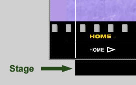
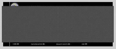
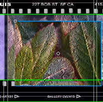
- Make sure the image is selected. Then use the arrow keys on the keyboard to slide the image up and to the left until the first two sprocket holes- are outside the left edge of the Stage, as shown in Figure 4-2b.
Stage
FIGURE 4-2b:
Aligning the comp image
- On the Align panel, toggle the To Stage button on and click Align vertical center to center the filmstrip image vertically.
- Click the Comp Image layer to select it.
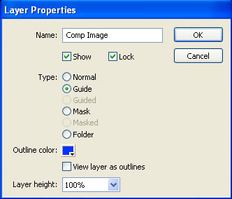
- Click the Modify menu, point to Timeline, and then click Layer Properties. The Layer Properties dialog box opens.
- Set the layer Type to Guide.
Note:
A guide layer will not show up in the preview or published documents.
- Lock the layer by clicking the Lock check box, as shown in Figure 4-2c. Click OK.
FIGURE 4-2c:
The Layer Properties box with the layer locked
- Click the Insert Layer button to create a new layer. Rename the new layer Background.
- Making sure this layer is still selected, select the Rectangle tool.
- Set the stroke and fill colors to black (#0000000).
- Draw a rectangle on top of the filmstrip. Make it approximately the same size (you'll adjust it more precisely in the next step). You might need to zoom out to see the entire filmstrip.
- Use the Selection tool to select the rectangle. Make sure to double-click to select both the fill and stroke.
- On the Property inspector, make sure the height and width boxes are unlocked. You can lock or unlock them by clicking the padlock icon. Locking them constrains the height and width proportions.
- Set W: to 1090 and H: to 360, and press Enter (Windows) or Return (Macintosh). The rectangle is sized to cover a large background area.
- With the rectangle still selected, center it vertically on the Stage using the Align panel. Use the arrow keys to center the rectangle horizontally over the comp image, as shown in Figure 4-2d.
FIGURE 4-2d:
Background rectangle centered over comp image
- Convert the rectangle into a graphic symbol (from the Modify menu) and name it Background.
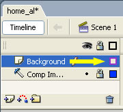
- Click the Show As Outline button (the square to the right of the padlock shown in Figure 4-2e) for the Background layer. The black background appears as an outline only so it is no longer blocking the comp image.
FIGURE 4-2e:
Show the Background layer as an outline
- Save your changes and remain in this screen for the next Step-by-Step.
Creating the Filmstrip Sprocket Holes
The sprocket holes are important to your overall design. They make the words and the
images seem like part of a filmstrip. If you were to draw so many sprocket holes individually, it would take a long time and unnecessarily increase the file size. You can use a single sprocket hole symbol to create the entire row.
-
STEP-BY-STEP 4.3: Creating the Filmstrip Sprocket Holes
- Insert a new layer and name it Sprocket Holes.
- Make sure the layer is selected. On the File menu, point to Import, click Import to Stage, and import sprocketHole.jpg from the Images folder in the build_GallerySanLuis folder.
- Double-click the sprocket hole image to make sure it is selected. A gray outline appears around the sprocket hole.
- Convert the sprocket hole to a movie clip symbol and name it Sprocket Hole.
Hot Tip: You could have made the sprocket hole a graphic or even a button symbol, but a movie clip gives you the most flexibility for animation and interaction purposes. In any case, it is easy to change a symbol's behavior later on the Property inspector.
- Because there are 32 sprocket holes in each row, drag 31 more instances of the Sprocket Hole movie clip from the Library to the Stage in the Sprocket Holes layer (anywhere will do - do not try to line them up yet!) (You might need to open the Library panel from the Window menu.) Instances of the Sprocket Hole symbol accumulate on the Stage. Make sure all of them are on the Sprocket Holes layer.
FIGURE 4-3a:
Dragging 32 sprocket holes
- Drag one of the sprocket holes to just below the right sprocket hole at the top of the filmstrip (visible from the Comp Image layer) and drag another sprocket hole to just below the far left sprocket hole at the top of the filmstrip. These are the two endpoints for the row of sprocket holes you are about to create, as shown in Figure 4-8.
FIGURE 4.3b:
Creating a row of sprocket holes
- Select all the sprocket holes by clicking on the first frame of the Sprocket Holes layer.
- On the Align panel, toggle the To Stage button to off.
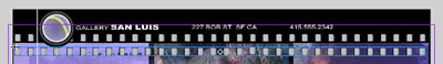
- Click the Space evenly horizontally button and then click the Align top edge button. The sprocket holes align in a row, as shown in Figure 4-3c.
FIGURE 4-3c:
Aligned sprocket holes
- Convert this row of sprocket hole instances into its own movie clip symbol and name it Sprocket Hole Row, as shown in Figure 4-10.
FIGURE 4-3d:
Sprocket Hole Row movie clip
You now have reached the third level of symbols: The main movie (home.fla) level within which there is a Sprocket Hole Row movie clip, within which there are 32 Sprocket Hole movie clips. Part of the power of movie clip symbols is that each sprocket hole symbol has an independent Timeline.
- Align the Sprocket Hole Row movie clip over the top row of sprocket holes visible from the Comp Image layer. Align them as well as possible, using the arrow keys on the keyboard and zooming in if necessary.
- Drag another instance of the Sprocket Hole Row movie clip onto the Stage from the library.
- Cover the lower row of sprocket holes visible from the comp image as well as possible.
- Save the movie and remain in this screen for the next Step-by-Step.
Inserting and Placing Images
Now you're ready to insert the images. When you are working in Flash and you are concerned about precise placement of elements on the Stage, you can use rulers and draggable guides.
-
STEP-BY-STEP 4.4: Using Rulers and Guides and Inserting Images
- Click the View menu and then click Rulers. Rulers appear above and to the left of the Stage.
- On the View menu, point to Snapping, and make sure Snap to Objects and Snap to Guides are selected. Then, point to the Guides option on the View menu, and make sure Show Guides is selected. You will use these guides to align the inserted pictures on the three content areas of the filmstrip.
- Drag a guide onto the Stage by clicking on the ruler at the top of the work area and dragging down toward the Stage without releasing your pointer. You might have to zoom in to align the guides correctly. A green line appears on the Stage. This is your guide line.
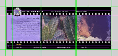
- Position the first guide so it is right on the top border of the three filmstrip "cels." Then drag another 11 guides to frame the three filmstrip cels and the Stage, as shown in Figure 4-4a. You might have to hide the Comp Image layer to see the Stage. You might also want to zoom in so you can line up the guides precisely.
The boxes in the filmstrip are referred to as "cels." This name comes from the fact that animated cartoons were originally drawn on celluloid.
FIGURE 4-4a:
Lining up the guides
- On the View menu, point to Guides, and then click Lock Guides.
Now, you insert images along the guides.
- Create a new layer and name it Center.
- Import the image floral.jpg from the images folder into this layer.
- Convert the image into a graphic symbol and name it Home Center.
- On the Property inspector, set the width to 345 and the height to 260.
- Drag Home Center up against the guides in the center cel. Use the Arrow keys to adjust the position of the images, as shown in Figure 4-4b.
FIGURE 4-4b:
Aligning an image with the guides
- Insert a new layer above Center and name it Right.
- Import the image portrait.jpg from the images folder into this layer.
- On the Property Inspector, Set W: to 345 and H: to 260.
- Convert the image to a graphic symbol and name it Home Right.
- Align the image to the guides in the cel on the right.
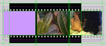
- Insert a new layer above Right and name it Left.
- Select the Rectangle tool. Change the Stroke to None and the Fill to purple #9933FF, as shown in Figure 4-13.
- Draw a rectangle approximately the same size as the left cel. The rectangle should "snap" to the guides. That is a major advantage of working with guides: creating precise drawing objects. If necessary, use the Property inspector to change the size of the rectangle to 345 x 260. Use the Arrow keys to adjust its position in the left cel if necessary.
FIGURE 4-4c:
Drawing a purple (#9933FF) rectangle in the Left cel
- Convert the rectangle to a movie clip symbol and name it Home Left Background.
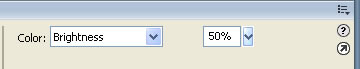
- On the Property inspector, select the Color drop-down box and set the Brightness to 50%.
FIGURE 4-4d:
Property inspector showing Color drop down Brightness set at 50%
- Save your work and remain in this screen for the next Step-by-Step.
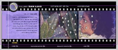
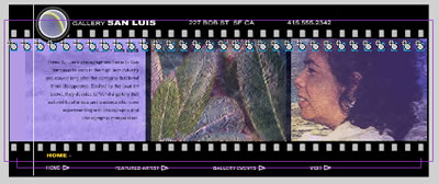
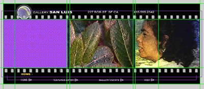
FIGURE 4-4e:
Gallery San Luis Home Page, so far
Creating a Template Movie Clip
Because you will be creating many similar 345 x 260 cels for content later, it might be a good idea to create a template movie clip. Then you can just duplicate this movie clip in the library when you need to create new content.
-
STEP-BY-STEP 4.5: Creating a Movie Clip for Future Content
- Locate the Library panel (or, if necessary, open it) that contains all the symbols.
- Click the Home Left Background symbol once to select it
- From the Options menu in the upper-right corner of the Library panel, choose Duplicate
- Name the new symbol Cel Background and click OK.
- Double-click the icon beside the Cel Background movie clip in the library. This opens the Cel Background movie.
- Rename Layer l Background.
- Use the Selection tool to double-click the rectangle.
- On the Property inspector, change the Fill color to gray (#CCCCCC).
- Click Scene 1 on the information bar to return to the main Timeline.
- Save the document, then close the file and exit Flash.
 Back to previous page: Lesson 3: Creating a Logo Back to previous page: Lesson 3: Creating a Logo
 After this lesson, you should complete the following After this lesson, you should complete the following
- Test on Flash Lesson 4: Designing a Home Page
- Project
Go to next section: Lesson 5: Adding Text and Navigation
|